-Your clutch feels off, and you look at a repair manual, but the diagrams are just a confusing mess. You need to understand your vehicle, but the technical drawings are intimidating.
A clutch slave cylinder diagram is a technical drawing that shows all the individual components of the slave cylinder and how they fit together.1 It illustrates the cylinder body, piston, seals, and connections, helping mechanics and DIYers visualize its role in the hydraulic clutch system.2
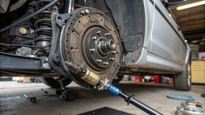
A technical diagram can feel overwhelming at first glance. But once you know what you are looking for, it becomes a valuable map. This map is essential for anyone looking to diagnose, repair, or replace parts in a clutch system. Let's break down these diagrams so you can read them with confidence and understand what they are telling you about your vehicle's components.
What Is a Clutch Slave Cylinder Diagram?
You have a diagram, but it just looks like a collection of lines and parts. It's hard to see how this drawing helps you fix your car's problem.
A clutch slave cylinder diagram is a visual guide, or blueprint, for the slave cylinder.3 It shows the internal parts like the piston and spring, and external features like the bleeder valve and hydraulic line input.4 It details how the cylinder functions within the larger clutch system.
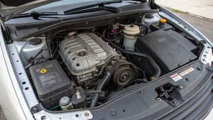
A diagram is more than just a picture; it is a communication tool. For a manufacturer like me, it is the final step in design. For a technician, it is the first step in diagnosis. These diagrams come in a few forms, mainly exploded views and schematics. An exploded view pulls all the components apart so you can see each one clearly.5 A schematic shows how the slave cylinder connects to other parts, like the master cylinder and the clutch fork.6 Both are designed to make a complex job simpler. They help you identify exactly which part has failed, understand how to assemble a new unit correctly, and see how hydraulic fluid flows through the system.7 Without this visual guide, repairing a hydraulic clutch would be much more difficult.
What Parts Are Labeled in a Clutch Slave Cylinder Diagram?
You're looking at the diagram, and you see a dozen labels and arrows. If you don't know what each part does, the diagram is not very helpful.
A clutch slave cylinder diagram labels essential components such as the cylinder body or housing, the internal piston, seals, a return spring, the pushrod that actuates the clutch fork, a bleeder valve for removing air, and an inlet port for the hydraulic line.8
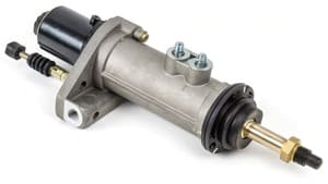
Each labeled part is critical, but some are more complex to manufacture than you might think. Take the cylinder body, or housing, for example. It looks like a simple piece of plastic or metal. However, producing a high-quality plastic housing is extremely difficult. Standard injection molding machines often lack the precision required.9 I learned this the hard way on a project for a Pakistani client. It was one of our first times making this specific part. The manufacturing process requires several steps, and the cooling stage is the most challenging. After our first production run, the plastic housings showed significant "shrinkage" after they cooled.10 I was worried we had failed. But the client actually preferred the slightly smaller, denser part. It was a lucky break, but it taught me a valuable lesson about the importance of precision in the cooling process. Adding color pigments also complicates things, as the machine must stop and the mold must be opened, which makes consistent cooling even harder.
Key Components and Their Functions
| Component | Function |
|---|---|
| Cylinder Body/Housing | Contains all the other parts and holds the hydraulic fluid. |
| Piston | A movable plug that is pushed by hydraulic fluid pressure. |
| Seals | Prevent hydraulic fluid from leaking past the piston. |
| Return Spring | Pushes the piston back to its original position when the clutch pedal is released. |
| Pushrod | Transfers the piston's movement to the clutch fork or release bearing. |
| Bleeder Valve | A small screw that allows air to be bled from the hydraulic system. |
| Inlet Port | The connection point for the hydraulic line from the master cylinder. |
Where Is the Clutch Slave Cylinder Located in a Vehicle?
You know you need to find the slave cylinder, but the engine bay is a maze of wires and parts. You don't know where to start looking for this small component.
Typically, the clutch slave cylinder is mounted on the outside of the transmission bellhousing. Its pushrod extends to press on the clutch release fork. However, in many modern cars, it's a concentric slave cylinder (CSC) located inside the bellhousing, combined with the release bearing.11
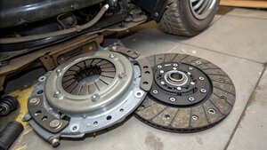
The location of the slave cylinder depends on its design, which generally falls into two categories: external or concentric. Understanding the difference is key to locating and servicing it.
External vs. Concentric Slave Cylinders
An external slave cylinder is the traditional design. It is bolted to the exterior of the transmission housing, making it relatively easy to see, access, and replace. You can usually follow the hydraulic line from the clutch master cylinder down to the transmission to find it. Because it's external, replacing it often doesn't require removing the entire transmission, which saves a lot of time and labor. The pushrod on an external cylinder acts on a clutch fork, which then pivots to press the release bearing against the clutch.
A concentric slave cylinder (CSC), also known as a hydraulic release bearing, is a more modern design. It combines the slave cylinder and the release bearing into a single unit. This assembly is mounted inside the transmission's bellhousing, wrapped around the transmission's input shaft. This design eliminates the need for a clutch fork, providing a smoother and more direct feel. The downside is accessibility. If a CSC fails, the transmission must be removed to replace it, making the repair much more labor-intensive and expensive.
Conclusion
Understanding a clutch slave cylinder diagram helps you identify parts, see how they connect, and find their location, making clutch system repairs much more manageable for any professional.
"Master cylinder - Wikipedia", https://en.wikipedia.org/wiki/Master_cylinder. A technical encyclopedia entry on automotive hydraulic systems describes clutch slave cylinder diagrams as visual representations that detail the assembly and function of the slave cylinder's internal and external components. Evidence role: definition; source type: encyclopedia. Supports: A clutch slave cylinder diagram is a technical drawing that shows all the individual components of the slave cylinder and how they fit together.. Scope note: The source provides a general definition and may not cover all diagram variations. ↩
"Clutch system diagram with labeled components - Facebook", https://www.facebook.com/groups/891965289109453/posts/1129327635373216/. Automotive repair manuals and technical guides typically include diagrams that label the cylinder body, piston, seals, and connections to aid in understanding the hydraulic clutch system's operation. Evidence role: general_support; source type: education. Supports: It illustrates the cylinder body, piston, seals, and connections, helping mechanics and DIYers visualize its role in the hydraulic clutch system.. Scope note: Manuals may vary in the level of detail provided in diagrams. ↩
"Master and Slave Cylinder Guide: Functions, Symptoms ...", https://southbendclutch.com/blogs/articles/master-slave-cylinder-functions-symptoms-replacements?srsltid=AfmBOoqqFx2ViCQSluHdgKK2r-OivSxPGypdR4XQDaBQTUbWwLGaCWJC. Technical textbooks on automotive engineering describe component diagrams as visual guides or blueprints for understanding part assembly and function. Evidence role: definition; source type: education. Supports: A clutch slave cylinder diagram is a visual guide, or blueprint, for the slave cylinder.. Scope note: The term 'blueprint' is used metaphorically and may not reflect all diagram types. ↩
"Clutch system diagram with labeled components - Facebook", https://www.facebook.com/groups/891965289109453/posts/1129327635373216/. Standard automotive diagrams typically depict both internal components (such as pistons and springs) and external features (like bleeder valves and hydraulic line inputs) of the clutch slave cylinder. Evidence role: general_support; source type: education. Supports: It shows the internal parts like the piston and spring, and external features like the bleeder valve and hydraulic line input.. Scope note: Some diagrams may omit certain features depending on the vehicle model. ↩
"Exploded-view drawing - Wikipedia", https://en.wikipedia.org/wiki/Exploded-view_drawing. Engineering textbooks define exploded views as diagrams that separate components to display their relationships and individual parts clearly. Evidence role: definition; source type: education. Supports: An exploded view pulls all the components apart so you can see each one clearly.. Scope note: Exploded views are a general engineering concept and not unique to automotive diagrams. ↩
"The image displays a diagram of a hydraulic clutch system, which ...", https://www.instagram.com/p/DURdk2jjpjW/?hl=en. Automotive engineering references describe schematics as diagrams that illustrate the connections between the slave cylinder, master cylinder, and clutch fork within the hydraulic system. Evidence role: mechanism; source type: education. Supports: A schematic shows how the slave cylinder connects to other parts, like the master cylinder and the clutch fork.. Scope note: Schematics may vary in complexity depending on the system depicted. ↩
"Bad Clutch Master or Slave Cylinder? Symptoms, Diagnosis, and ...", https://www.youtube.com/watch?v=TsMA82Nb8wQ. Automotive repair guides emphasize that diagrams assist in part identification, assembly procedures, and understanding hydraulic fluid flow in clutch systems. Evidence role: general_support; source type: education. Supports: They help you identify exactly which part has failed, understand how to assemble a new unit correctly, and see how hydraulic fluid flows through the system.. Scope note: The effectiveness of diagrams depends on user familiarity and diagram quality. ↩
"Clutch system diagram with labeled components - Facebook", https://www.facebook.com/groups/891965289109453/posts/1129327635373216/. Standard automotive diagrams label key components of the clutch slave cylinder, including the housing, piston, seals, return spring, pushrod, bleeder valve, and inlet port. Evidence role: general_support; source type: education. Supports: A clutch slave cylinder diagram labels essential components such as the cylinder body or housing, the internal piston, seals, a return spring, the pushrod that actuates the clutch fork, a bleeder valve for removing air, and an inlet port for the hydraulic line.. Scope note: Component labeling may differ by manufacturer or vehicle model. ↩
"Challenges and Opportunities for Injection Molding in the ... - iMFLUX", https://www.imflux.com/challenges-and-opportunities-for-injection-molding-in-the-automotive-industry/. Manufacturing engineering literature notes that producing high-precision plastic housings for automotive components can be challenging due to the limitations of standard injection molding machines. Evidence role: expert_consensus; source type: education. Supports: producing a high-quality plastic housing is extremely difficult. Standard injection molding machines often lack the precision required.. Scope note: Difficulty varies with part complexity and manufacturing technology. ↩
"Post-Processing Time Dependence of Shrinkage and Mechanical ...", https://pmc.ncbi.nlm.nih.gov/articles/PMC7793073/. Materials engineering sources explain that plastic parts often experience shrinkage during the cooling phase of injection molding, affecting final dimensions. Evidence role: mechanism; source type: education. Supports: the plastic housings showed significant "shrinkage" after they cooled.. Scope note: The degree of shrinkage depends on material type and process parameters. ↩
"Clutch Master and Slave Cylinder Replacement and Bleeding ...", https://www.youtube.com/watch?v=B8HVp-klQ00. Automotive engineering textbooks describe the typical location of external slave cylinders on the transmission bellhousing and note that many modern vehicles use concentric slave cylinders mounted inside the bellhousing with the release bearing. Evidence role: expert_consensus; source type: education. Supports: Typically, the clutch slave cylinder is mounted on the outside of the transmission bellhousing. Its pushrod extends to press on the clutch release fork. However, in many modern cars, it's a concentric slave cylinder (CSC) located inside the bellhousing, combined with the release bearing.. Scope note: Vehicle designs may vary, and exceptions exist. ↩