
Feeling those rough shifts? The complex valve body is a likely suspect. A diagram is your map, but it's often hard to read.
A valve body diagram1 is a technical map of your transmission's control center. It shows fluid channels2, valves, and solenoids3. Technicians use it to trace hydraulic circuits4 and accurately diagnose shifting problems and performance issues.
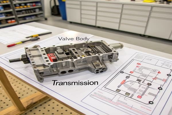
These diagrams are more than just lines on a page; they are the key to understanding and fixing complex transmission behavior. Let's break down what they show and why they are so critical for any serious repair work.
What Is a Valve Body Diagram and Why Do Technicians Search for It?
Can't figure out a tricky transmission fault? General advice isn't working. You need a detailed schematic to find the real problem.
A valve body diagram1 is a blueprint of the hydraulic control system5. It shows every passage, valve, and solenoid. Technicians search for it to visually trace fluid flow and pinpoint the exact cause of shifting errors.
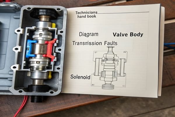
The valve body is often called the "brain" of the automatic transmission. It directs hydraulic fluid to control which gear is engaged. The diagram is the language this brain speaks. Without it, a technician is just guessing. In our manufacturing work, we know that creating these diagrams is incredibly difficult. The precision required is immense. High-end drawing software is a must, the kind you find in specialized factories around Shanghai or Fujian. A simple tool from a small workshop in a place like Hebei just won't cut it. The diagram must be perfect to be useful for accurate diagnostics and repairs. It's the foundation for any successful transmission work.
The Role of a Diagram in Diagnostics
| Approach | Without a Diagram | With a Diagram |
|---|---|---|
| Diagnosis | Guesswork based on symptoms | Precise tracing of fluid paths |
| Repair Time | Long, involves trial and error | Faster, targeted part replacement |
| Accuracy | Low, risk of misdiagnosis | High, confirms the fault location |
| Cost | Potentially high due to wrong parts | Lower, replaces only the failed part |
How Can a Valve Body Diagram Help Identify Solenoids and Fluid Channels?
Looking at a valve body feels like staring at a metal maze. Finding the right solenoid is a huge challenge. One mistake is expensive.
A good diagram acts as a clear legend. It assigns a name and function to every solenoid and valve. It also traces the winding fluid channels2, showing you exactly how pressure moves to activate different clutches.
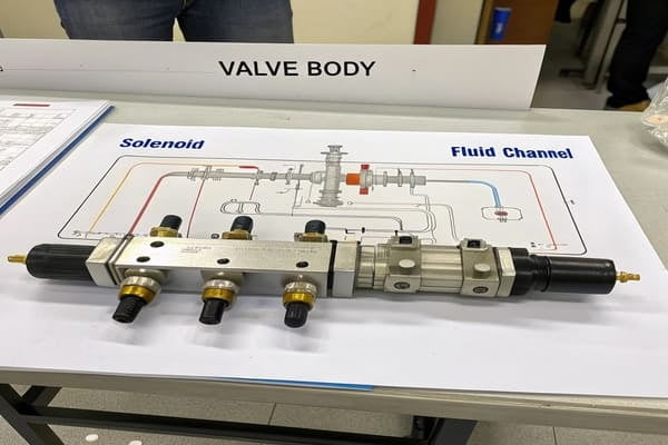
The diagram is your guide. It points out the TCC (Torque Converter Clutch6) solenoid, the shift solenoids7s](https://www.mistertransmission.com/transmission-solenoid/)%%%FOOTNOTE_REF_3%%% (like Solenoid A, B, C), and the pressure control solenoid8ds](https://www.mistertransmission.com/transmission-solenoid/)%%%FOOTNOTE_REF_3%%%. More importantly, it shows the paths the transmission fluid takes. From my experience, accurately marking these oil circuit paths is the hardest part of creating a diagram. There are at least three major steps in the drafting process, and getting the fluid flow right is the most complex. The lines on the page represent real, pressurized fluid that makes the transmission work. If you can't follow that path on paper, you have no chance of fixing it in the real world.
Decoding the Symbols and Lines
| Component | Common Label | Function in Diagram |
|---|---|---|
| Shift Solenoid | SS-A, SS-1 | Labeled to show which gear it controls |
| Pressure Control Solenoid | PCS, EPC | Shows how line pressure is regulated |
| Fluid Channel | Solid or Dashed Lines | Traces the path of hydraulic fluid for a specific gear |
| Check Ball | Small Circle | Indicates a one-way valve in a fluid path |
Which Valve Body Diagram Details Matter Most During Diagnosis?
You have a transmission fault code9, but where do you start looking? Wasting time and money on the wrong component is painful.
During diagnosis, focus on three things: the locations of check balls10, the specific fluid circuits tied to the fault code9, and the solenoid positions. These details connect the electronic error directly to a physical part.
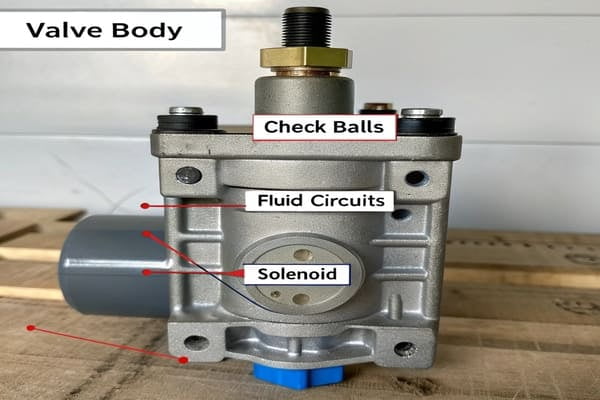
Matching a fault code9 to a physical location is the toughest part of using a diagram. It’s a very specific process. Often, the diagnostic software11 has to be paused, and you have to open the transmission fault code9 library separately to cross-reference the information. This can make a precise diagnosis tricky. I learned this the hard way on a project with a client from Pakistan. It was our first time providing a diagram service, and frankly, we didn't have enough experience. The diagram we made caused several "fault misjudgments" in the workshop. Luckily, the client found it perfect for his training and demonstration scenarios, so he was happy. It taught me a valuable lesson: for real-world repairs, absolute precision is everything.
From Fault Code to Physical Part
| Diagnostic Step | Why the Diagram is Crucial |
|---|---|
| Read Fault Code (e.g., P0751) | The diagram helps locate "Shift Solenoid A". |
| Test Solenoid Circuit | It identifies the solenoid's physical position on the valve body. |
| Check Hydraulic Path | It shows the fluid channels2 controlled by that solenoid. |
| Inspect for Blockages | It points to relevant check balls10 or valves in that specific circuit. |
How Do Valve Body Diagrams Differ Across Automatic and DSG Transmissions?
Think all transmission schematics are the same? Using an old automatic diagram for a modern DSG will cause major problems.
Diagrams for traditional automatics focus on hydraulic control for a torque converter and planetary gearsets. DSG (or Mechatronic) diagrams are far more complex. They show control for two separate clutches and integrate electronic control logic.
The core technology is different, so the diagrams have to be different. A classic automatic transmission uses fluid pressure to engage clutch packs within a planetary gear system. A DSG, on the other hand, is more like two manual gearboxes in one, and its Mechatronic unit uses hydraulics to operate the dual clutches and shift forks. This means the diagram for a DSG is not just a hydraulic map; it's an electro-hydraulic map12. It shows how the integrated Transmission Control Module (TCM) commands the solenoids3 to manage the clutches. As an OEM supplier, we handle both. We see firsthand how DSG Mechatronic units demand a much deeper integration of electronics, sensors, and fluid dynamics. The diagrams reflect this complexity.
Comparing Hydraulic vs. Mechatronic Schematics
| Feature | Traditional Automatic Valve Body | DSG Mechatronic Unit |
|---|---|---|
| Main Component | Torque Converter | Dual Clutches |
| Control Logic | Mostly Hydraulic | Electro-Hydraulic |
| Diagram Focus | Fluid circuits for planetary gears | Solenoid control of clutches and shift forks |
| Complexity | High | Extremely High (integrated electronics) |
Conclusion
A valve body diagram1 is an essential, complex tool. Understanding it is not just helpful; it is absolutely necessary for accurate and efficient transmission diagnosis and repair.
Explore this link to understand the significance of valve body diagrams in diagnosing transmission issues. ↩
Understanding fluid channels is crucial for diagnosing and repairing transmission issues. ↩
Discover the importance of solenoids in transmission systems and their impact on performance. ↩
Understanding hydraulic circuits is key to mastering transmission repair techniques. ↩
Learn about hydraulic control systems to grasp their role in transmission functionality. ↩
Gain insights into the Torque Converter Clutch's role in transmission efficiency. ↩
Explore the function of shift solenoids to better understand gear shifting mechanisms. ↩
Learn about pressure control solenoids to enhance your knowledge of transmission systems. ↩
Explore fault codes to understand how they help in diagnosing transmission problems. ↩
Understanding check balls is essential for accurate transmission diagnostics. ↩
Explore the role of diagnostic software in enhancing repair accuracy and efficiency. ↩
Discover the significance of electro-hydraulic maps in modern transmission systems. ↩