
Are you confused by complex brake caliper diagram1s? They seem technical and hard to read. But they hold the key secrets to a vehicle's braking power and reliability.
A brake caliper diagram1 is a technical blueprint that reveals how braking forces2 are applied, how heat is managed, and the caliper's fundamental design (floating vs. fixed). These details directly dictate stopping power, brake feel, and component wear3, making the diagram essential for performance analysis4.
Understanding these diagrams is not just for engineers. As a business that develops and supplies automotive parts, reading these blueprints is a core part of my job. It helps us create better products for our partners. Let's walk through how to decode these diagrams so you can see what I see.
What Does a Brake Caliper Diagram Really Explain About Braking Performance?
Looking at a brake caliper diagram1 can feel like staring at a puzzle. You see lines and shapes, but miss the story they tell about performance.
A caliper diagram explains performance by showing the force distribution path5, from hydraulic pressure6 to the brake pads7. It also illustrates the caliper's structural rigidity8 and piston layout9, which are critical factors for achieving consistent and powerful braking under load.
Creating and interpreting these diagrams is a highly skilled task. I learned this the hard way. Early in my career, we took on a project for a German client. We used standard software, and the resulting diagram had what we call "force display deviation." The paths showing how the braking force traveled were not accurate. We thought it was a failure. Luckily, the client needed it for a teaching demonstration, and the exaggerated error actually helped them explain the concept better. We got lucky. That experience taught me that creating a truly accurate diagram is incredibly difficult.
The Challenge of Force Path Visualization
The hardest part of making a good diagram is mapping the braking force path. This shows how hydraulic fluid pressure10 is converted into a physical clamping force on the brake rotor. It requires specialized software, usually found only in top-tier design studios, not smaller workshops. The process is so precise that it must account for tiny flexes in the caliper body11 under extreme pressure. An inaccurate path can mislead you about how evenly the brake pads7 will wear and how firm the brake pedal will feel.
Annotating Hydraulic Logic
Another major challenge is adding the hydraulic logic annotations12. To do this, the designer has to pause the dynamic simulation and switch layers in the software to add notes. This process can easily break the logical flow of the diagram if not handled by an expert. The annotations must clearly show how fluid enters, builds pressure, acts on the piston, and retracts. Without this clarity, the diagram is just a picture of parts, not a functional explanation. It’s this functional detail that separates a basic drawing from a professional engineering document.
What Parts Are Shown in a Brake Caliper Diagram and What Does Each One Do?
A caliper diagram is filled with many different components. It is easy to get lost if you do not know what you are looking for.
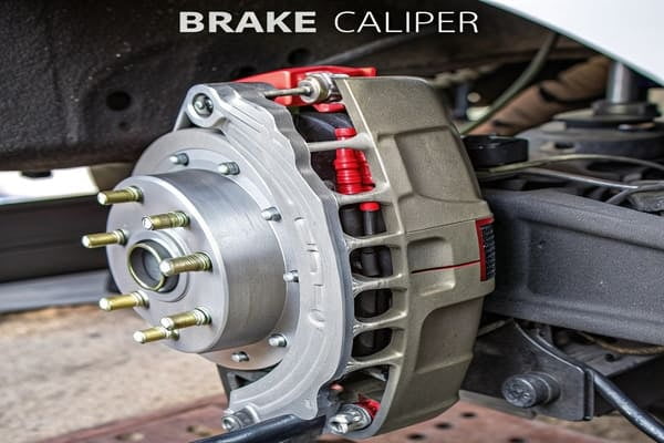
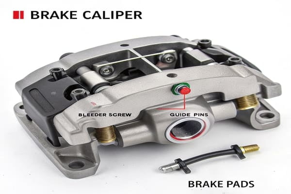
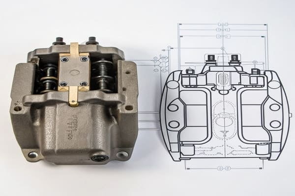
A standard brake caliper diagram1 shows the caliper body11, piston(s), seals, bleeder screw13, guide pins14, and brake pads7. Each part has a specific job, working together to convert hydraulic pressure6 into the friction that stops your vehicle.
To truly understand how a caliper works, you need to know what each of these parts does. A caliper is a great example of a simple machine, but its effectiveness depends on every single component functioning perfectly. In our OEM/ODM work15, we focus on the material quality and dimensional accuracy of every part, because a failure in one small seal can compromise the entire braking system. Let's break down the core components and their roles.
Core Components and Their Roles
Each part in a caliper diagram has a critical function. Understanding these functions is the first step to diagnosing problems or evaluating a caliper's design for a specific application. Whether we are designing a caliper for a heavy-duty truck or a performance car, the fundamental roles of these parts remain the same.
| Component | Function in the System |
|---|---|
| Caliper Body | The main structural housing. It holds the piston(s) and brake pads7 and is mounted to the vehicle's suspension knuckle. |
| Piston(s) | A cylindrical part that is forced outward by hydraulic fluid pressure10. It directly pushes the inboard brake pad against the rotor. |
| Piston Seal | A square-cut rubber ring inside the caliper bore. It prevents brake fluid from leaking past the piston and helps retract the piston when the brakes are released. |
| Dust Boot | A rubber cover that protects the piston and its seal from contamination like road grime, water, and salt, which can cause seizing. |
| Bleeder Screw | A small valve that allows air to be purged (bled) from the hydraulic system, ensuring a firm brake pedal. |
| Guide/Slide Pins | Used only in floating calipers. These pins allow the caliper body11 to slide side-to-side, enabling it to clamp the rotor evenly. |
| Brake Pads | The friction material bonded to a steel backing plate. They are the components that make contact with the rotor to create friction. |
How Does a Brake Caliper Actually Work During Braking?
You press the brake pedal, and the car slows down. But what happens inside the caliper during those few seconds? The process is a mystery to many.
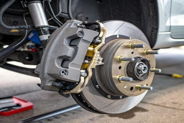
When you press the brake pedal, the master cylinder sends high-pressure hydraulic fluid to the caliper. This fluid pressure forces the caliper's piston to push the brake pads7 tightly against the spinning brake rotor, creating friction and heat to stop the car.
This process is a perfect example of hydraulics in action. It multiplies the force from your foot into a massive clamping force at the wheels. As a manufacturer, we are obsessed with this sequence. We ensure our caliper bores are perfectly smooth and our seals have the exact right elasticity. Any imperfection can introduce lag or weakness into the braking sequence16, which is unacceptable for our clients who depend on reliable, consistent performance.
The Hydraulic Force-Transfer Sequence
The entire braking event happens in a split second, following a precise chain of events. A diagram helps visualize this, but the real process is dynamic.
- Pedal Input: You press the brake pedal. This action pushes a rod into the master cylinder, pressurizing the brake fluid within the system.
- Fluid Transfer: This pressurized fluid travels instantly through the rigid brake lines and flexible hoses to each wheel's brake caliper.
- Piston Actuation: The fluid enters the caliper and exerts uniform pressure on the back of the piston(s). Because fluid is not compressible, this pressure forces the piston to slide outward.
- Pad-to-Rotor Contact: The piston pushes the inner brake pad until it makes firm contact with the brake rotor.
- Caliper Clamping Action: In a floating caliper, the caliper body11 then slides on its guide pins14, pulling the outer brake pad against the other side of the rotor. In a fixed caliper, a second set of pistons pushes the outer pad.
- Friction and Heat: With both pads now clamped onto the spinning rotor, immense friction is generated. This friction converts the car's kinetic energy (motion) into thermal energy (heat), which slows the vehicle down.
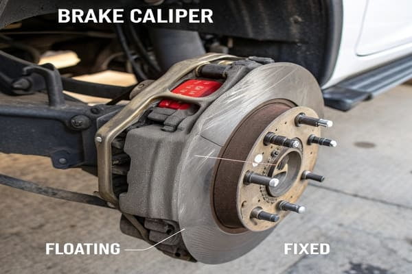
Why Do Floating and Fixed Brake Calipers Look Different in Diagrams?
You may notice that some caliper diagrams look simple and asymmetrical, while others look larger and symmetrical. This is not an accident. You are seeing two different designs.
Floating and fixed caliper diagrams look different because they function differently. A floating caliper diagram shows pistons on only one side, as the caliper body11 slides on pins. A fixed caliper diagram shows pistons on both sides and is bolted rigidly in place.
The choice between these two designs is one of the most important decisions in braking system development. It's a trade-off between cost, performance, and packaging. Most everyday cars use floating calipers because they are cost-effective and compact. Performance and heavy-duty vehicles often use fixed calipers for their superior rigidity and clamping force. For our wholesale and OEM clients, we offer development services for both types, tailoring the design to their target market and performance goals.
Comparing Floating vs. Fixed Caliper Designs
The visual differences in the diagrams point directly to fundamental differences in construction and performance. A trained eye can identify the caliper type instantly and know what to expect in terms of feel and capability.
| Feature | Floating Caliper | Fixed Caliper |
|---|---|---|
| Diagram Appearance | Asymmetrical, with one or two pistons visible on the inboard side. Shows guide pins14. | Symmetrical, with pistons visible on both inboard and outboard sides. No guide pins14. |
| Number of Pistons | Typically one or two pistons, all on one side. | Two, four, six, or more pistons, arranged in opposing pairs. |
| Mounting | The caliper body11 "floats" on guide pins14 or slides, allowing it to self-center. | The caliper body11 is bolted "fixed" and rigidly to the suspension knuckle. |
| Force Application | The piston pushes the inner pad, and the caliper body11 slides to pull the outer pad. | Opposing pistons push the inner and outer pads simultaneously. |
| Common Use | Standard passenger cars, light trucks. | Performance cars, race cars, heavy-duty trucks. |
| Key Advantage | Lower cost, simpler, and more compact packaging. | Higher clamping force, more even pad pressure, better pedal feel, superior heat dissipation. |
Conclusion
Brake caliper diagrams are more than technical drawings. They are a roadmap to performance, revealing the design's intent and capabilities. Understanding them helps you make better decisions for your business.
Explore this resource to understand the essential role of brake caliper diagrams in vehicle performance. ↩
Learn about the application of braking forces to enhance your understanding of vehicle dynamics. ↩
Understand the factors affecting component wear to improve maintenance practices. ↩
Gain insights into performance analysis techniques that can enhance braking efficiency. ↩
Explore the concept of force distribution to better understand braking mechanics. ↩
Discover the significance of hydraulic pressure in braking systems for improved vehicle safety. ↩
Learn about the critical function of brake pads in vehicle safety and performance. ↩
Learn about the importance of structural rigidity for reliable braking performance. ↩
Discover how piston layout influences braking efficiency and effectiveness. ↩
Explore the mechanics of hydraulic fluid pressure for a deeper understanding of braking systems. ↩
Understand the role of the caliper body to appreciate its importance in braking. ↩
Gain insights into hydraulic logic annotations for better diagram interpretation. ↩
Learn about the importance of bleeder screws for maintaining brake system integrity. ↩
Explore the function of guide pins to understand their role in brake caliper operation. ↩
Understand the importance of OEM/ODM work for quality automotive component production. ↩
Explore the braking sequence to understand the dynamics of vehicle stopping. ↩